


Antenna Cables


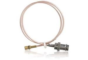


Very high quality RF antenna cables: Widest selection. Low signal loss.
Antenna Cable-Connectors' Gender is not as you would expect
- Gender of threaded connectors is referring to the pins inside--not the threads.
- This applies to all of the following: N, RP-SMA, RP-TNC, SMA, TNC
Connectors with "RP" in the name are further complicated by the "reverse polarization" (RP):
- The pins are female when they appear to be male, and vice versa.
- If the documentation refers to the connector as "reverse ____":
- This is the same as RP-____ (e.g, "reverse SMA" = RP-SMA)
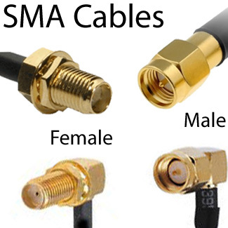
- RP-SMA-female has a pin RP-SMA-male has a socket
- SMA-female has a socket, SMA-male has a pin
- All of our cables with RP-SMA female have a bulkhead (nut and washer). They will will pass through an exterior wall covered in sheet metal and will seal out weather and survive extreme temperatures.
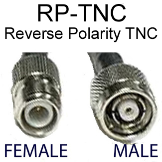
- RP-TNC-female has a pin RP-TNC-male has a socket
- TNC-female has a socket. TNC-male has a pin
Details about Reverse Polarity (RP) / Reverse Gender Connectors and Adapters (read more)
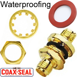
Waterproofing / Weatherproofing Connectors
Nickel-plated connectors and adapters (such as N) are the best for weather resistance. Gold-plated brass such as the SMA and RP-SMA connectors are not as weather-resistant as the nickel-plated ones. Over years exposed to weather, gold-plated brass connectors will show signs of gradual deterioration from the weather, if not protected.
Nickel will hold up with no signs of deterioration for years longer than gold-plated brass. Outdoor antennas with N-connectors are intended to be installed outdoors and exposed to the weather for many years, without any corrosion or deterioration, and this is the norm.
Gold-plated brass (SMA and RP-SMA) connectors are really intended for indoor use, although we very commonly have customers with outdoor installations using antennas and cables with Gold-plated brass SMA or RP-SMA connectors, just because the antenna and/or cable-connector suits a particular need better than using antennas and/or cables with N-connectors. In cases like this, they should use CoaxSeal to protect the gold-plated brass - especially for long-term exposure.
CoaxSeal is very low cost and we recommend as the solution for long-term outdoor exposure, that you wrap the connections with CoaxSeal:
- At the very least, wrap the SMA connections, and then for the sale of a super-durable solution
- If you want to have a super-durable long-term-exposure solution for a small incremental cost: Then also wrap the nickel-plated N-connectors and adapters.
See our Weatherproofing / Waterproofing products and solutions.
Signal Loss in Antenna Cables
Data Alliance uses low-loss double-shielded coaxial cable in all of our antenna cables, as opposed to the old standard, RG cable that is used in most other brands of antenna cables, and has a single layer of shielding.
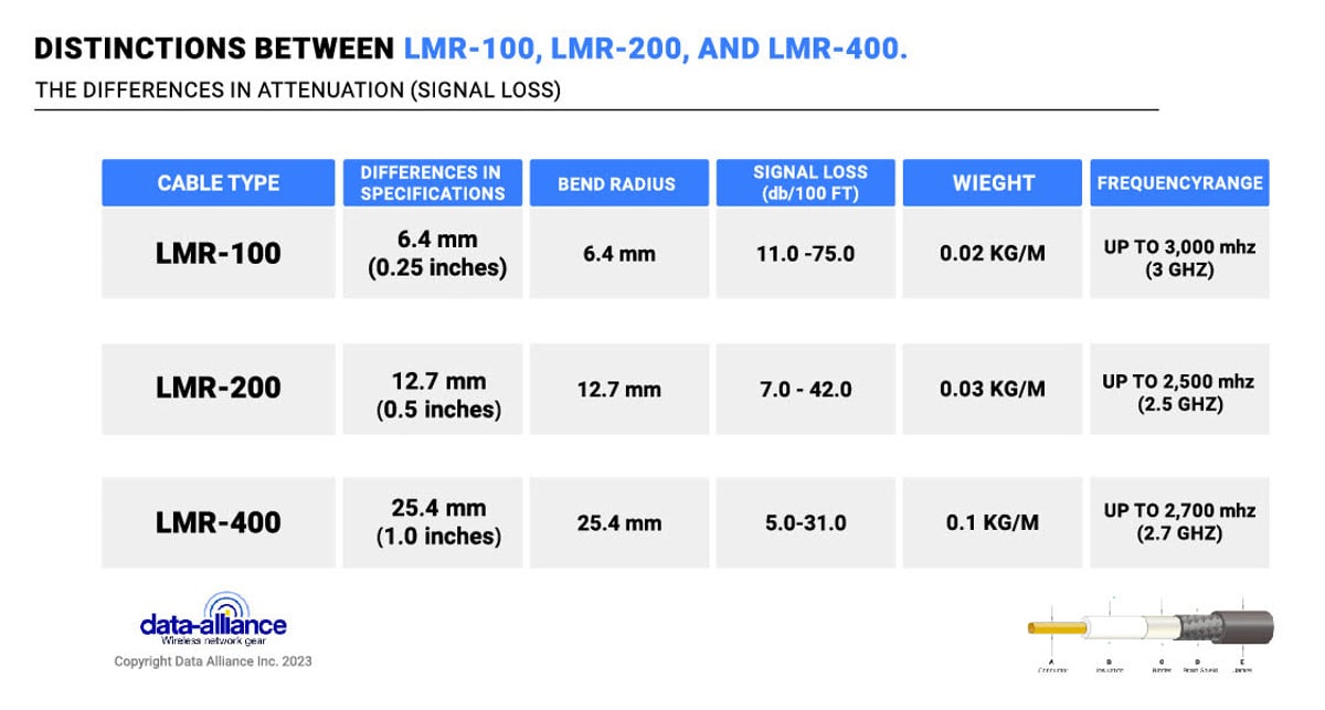
Data Alliance uses low-loss, double-shielded coaxial cable in all of our antenna cables, as opposed to the old standard, RG cable that is used in most other brands of antenna cables. These double-shielded coax types are 100-series, 200-series, and 400-series: 100-series is 0.10 inch in diameter, 200-series is 0.20 inch in diameter and 400-series is 0.4 inch in diameter. The term "low loss" antenna cables refers to the' low attenuation (loss) over distance, of the coaxial cable used in the antenna cable, relative to a typical old standard, RG cable.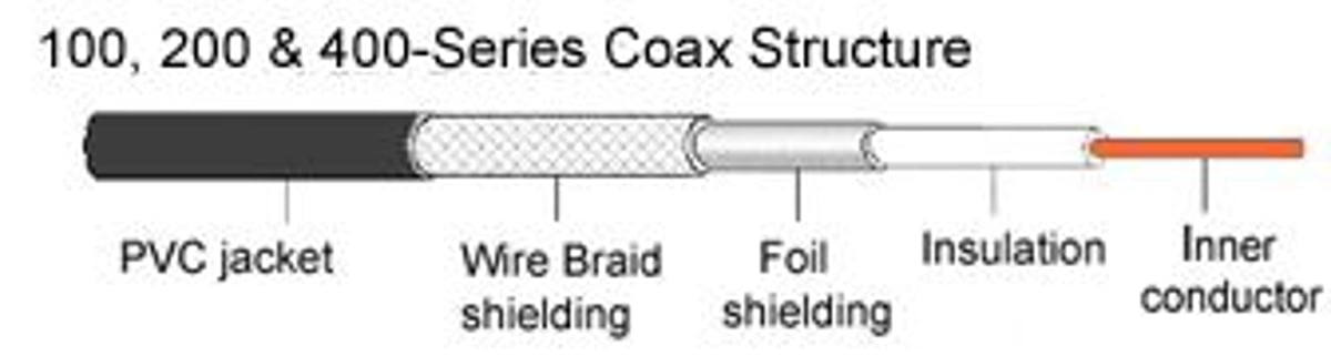
Low loss coaxial cable has far better shielding than typical RG style cable thus achieving better low loss characteristics. Additionally, low loss coaxial cables use solid center conductors which offer lower attenuation than stranded conductors that are sometimes found on RG style cables. Low loss coaxial cables are typically used in WLAN, Cellular, PCS, ISM and many other wireless applications The LMR-series coax is rated for outdoor use and are also suitable for indoor use Among the coax types below, the RG-series is the lowest quality and thinnest (RG174 & RG178, RG58). 100-series & 200-series tabs below include detailed specifications.
The attenuation rate per foot does not change with length of the cable: i.e., attenuation at 10 feet is 10x the attenuation at one foot, etc.
Attenuation In Coax For Antenna Cables: Signal strength is lost in the antenna cable: It is best to have the shortest cable that will serve your needs.
As coaxial antenna cable transfers radio frequency (RF) power from one point to another, the power that enters it is degraded along the length of the RF cable, meaning less power reaches the remote than entered the RF cable. This loss of power in the coax cable is what is referred to as attenuation. The loss is defined in terms of decibels/unit length at a given frequency:
Coax used in Data Alliance's antenna cables: We use low loss antenna cables for superior connection quality. Suited for indoor and outdoor use, our cables provide superior matching and loss values. Both connectors are soldered, not crimped, for the best possible signal quality.
Our shorter cables (less than two meters) we make with cable type equivalent to LMR100 or higher, in quality and signal-loss per meter. All of our cables of 2-meters or more are made from cable equivalent to LMR200 in quality and signal-loss per meter. The higher quality of the cable of our cables translates into lower sigal loss / better performance.
Our cables of 2-meters to 9-meters are made from cable-type equivalent to LMR200 in quality and signal-loss per meter. Longer cables made from cable-type equivalent to LMR400 The higher quality of the cable of our cables translates into lower signal loss & better performance.
SOLUTIONS FOR SIGNAL LOSS:
The solution is to reduce the length of antenna cables or eliminate them altogether, if possible: Bring the WiFi device as close as possible to the antenna.
Use one of the following solutions:
- For USB WiFi adapters: Use USB ccable(s) to set the USB WiFi adapter in the line of sight. You can use an outdoor enclosure to put the USB WiFi adapter outside, on a roof.
- For Access Point or Bridge: Ethernet cable with a Power Over Ethernet (POE) power supply. Ethernet cables can run as far as 175 feet with the power running over the ethernet cable. If your cable run is very long, use a higher-voltage POE such as 48-volt. Some voltage will be lost in the cable run, but if necessary you can use a voltage step-down adapter to bring the voltage down to what is required for your wireless device.

100-series attenuation at various frequencies 150MHz to 3000MHz: 100 meters
|
100-series Specifications & Attenuation (Signal Loss): |
|||||
|
|
|||||
|
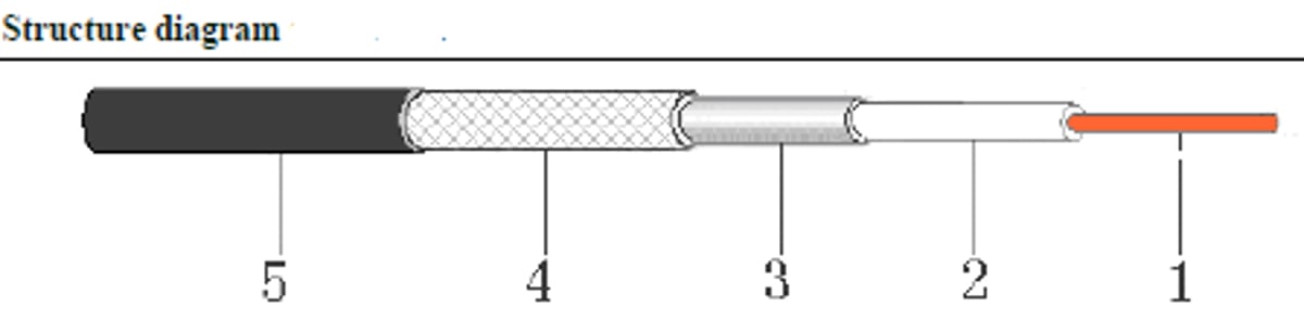
No. in diagram above: |
Item |
Structure |
Material |
Color |
|
|
1 |
Inner conductor |
0.45±0.02mm |
Bare copper |
Yellow |
|
|
2 |
Insulation |
1.50±0.10mm |
LDPE |
Nature |
|
|
3 |
Folia |
1.60±0.10mm |
Aluminum foil |
Silver gray |
|
|
4 |
Wire braid |
80*0.10mm |
Tinned copper |
Silver gray |
|
|
5 |
Jacket |
2.90±0.10mm |
PVC |
Black |
|
|
Attenuation (Signal Loss) at 20℃ (Max.) |
150MHz |
dB/100m |
32.3 |
||
|
200MHz |
dB/100m |
35.6 |
|||
|
400MHz |
dB/100m |
49.3 |
|||
|
1000MHz |
dB/100m |
80.6 |
|||
|
1500MHz |
dB/100m |
98.7 |
|||
|
2000MHz |
dB/100m |
115.5 |
|||
|
2500MHz |
dB/100m |
130.6 |
|||
|
3000MHz |
dB/100m |
142.4 |
|||
|
Electrical Physical and properties of product |
|||||
|
Item |
Unit |
Value |
|||
|
Capacitance |
pF/m |
100± 5 |
|||
|
Impedance |
W |
50± 2 |
|||
|
Velocity ratio |
% |
66 |
|||
|
Bent radius min |
mm |
15 |
|||
|
Max voltage |
VMS |
1500 |
|||
|
Max Frequency |
MHz |
3000 |
|||
|
Temperature scope |
℃ |
-20 ~ +80 |
|||

100-series has lower signal-loss than RG316
Temperature range for operational use of 100-series coax: -4 F ~ +176 F (--20°C ~ +80°C.)
100-series coaxial cable is used in short antenna cables (usually less than 7FT) Attenuation Per Foot in 100-series Coax: (black jacket)
- at 900 MHz: 0.23 db/ft
- at 2.4 GHz: 0.39 db/ft
- at 3.4GHz: 0.47 db/ft
- at 5.1-5.8GHz: 0.643 db/ft
| 200-Series Specifications & Attenuation (Signal Loss): | |||||
 |
|||||
| No. in diagram above: | Item | Structure | Material | Color | |
| 1 | Inner conductor | 1.12±0.02mm | Bare copper | Yellow | |
| 2 | Insulation | 2.95±0.10mm | Foam PE | White | |
| 3 | Folia | 3.07mm | Aluminum foil | Silver gray | |
| 4 | Wire braid | 96*0.12mm | Tinned copper | Silver gray | |
| 5 | Jacket | 5.00±0.10mm | PVC | Black | |
| Attenuation (Signal Loss) at 20C (Max.) | 200MHz | dB/100m | 16 | ||
| 400MHz | dB/100m | 24 | |||
| 900MHz | dB/100m | 33 | |||
| 1500MHz | dB/100m | 43 | |||
| 1800MHz | dB/100m | 47 | |||
| 2500MHz | dB/100m | 56 | |||
| Electrical Physical and properties of product | |||||
| Item | Unit | Value | |||
| Capacitance | pF/m | 81± 5 | |||
| Impedance | W | 50± 2 | |||
| Velocity ratio | % | 86 | |||
| Bent radius | mm | 25 | |||
| Max voltage | VMS | 1500 | |||
| Max Frequency | MHz | 3000 | |||
| Temperature scope | ℃ | -20 ~ +80 | |||
400-series: Attenuation Per Foot in 400-series Coax:
| Frequency (MHZ) | Attenuation dB/100ft. | Attenuation dB/100m. | Avg. Power kW |
|---|---|---|---|
| 30 | 0.7 | 2.2 | 3.33 |
| 50 | 0.9 | 2.9 | 2.57 |
| 150 | 1.5 | 5.0 | 1.47 |
| 220 | 1.9 | 6.1 | 1.20 |
| 450 | 2.7 | 8.9 | 0.83 |
| 900 | 3.9 | 12.8 | 0.58 |
| 1500 | 5.1 | 16.8 | 0.44 |
| 1800 | 5.7 | 18.6 | 0.40 |
| 2000 | 6.0 | 19.6 | 0.37 |
| 2500 | 6.8 | 2.22 | 0.33 |
| 5800 | 10.8 | 35.5 | 0.21 |
| 8000 | 13 | 42.7 | 0.17 |
RG-174 Attenuation Per Foot:
- at 900 MHz: 0.31447 db/ft
- at 2.4 GHz: 0.60237 db/ft
- at 3.4GHz: 0.76886 db/ft
- at 5.1-5.8GHz: 1.1134 db/ft
Double shielding of 100-series compared to single shielding of RG174.

RG178 Attenuation Per Foot: (RG178: clear jacket over copper braid)
- at 900 MHz: 0.55 db/ft
- at 2.4 GHz: 0.89 db/ft
- at 3.4GHz: 1.02 db/ft
- at 5.1-5.8GHz: 1.38 db/ft
RGB-58 Attenuation Per Foot:
- at 900 MHz: 0.1365 db/ft
- at 2.4 GHz: 0.258 db/ft
- at 3.4GHz: 0.328 db/ft
- at 5.1-5.8GHz: 0.479 db/ft
MORE ABOUT GENDER DETERMINATION: Details about Reverse Polarity (RP) / Reverse Gender Connectors and Adapters
- Reverse Polarity/Reverse Gender connectors satisfy FCC Regulation 15 by switching dielectrics and pins/contacts between genders.
- For example, a Reverse Gender Male consists of a male body, however, the dielectric and contact are female.
- Basically, an RP female will look like a standard male, and an RP male will look like a standard female. Reverse Polarity connectors and adapters will not mate with standard coaxial connectors. To attempt to do so will damage the connector.